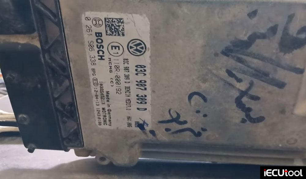
The goal is to bypass the immobilizer on a VAG Med17.1 ECU. The initial attempt to connect with CG FC200 programmer in “platform mode” failed, with the software stating, “ECU doesn’t support platform mode.” This necessitated a shift to a more involved “boot mode” process, which first requires reading the ECU’s security password.

There are 2 versions of boot mode wiring diagrams. First connected the hardware according to a standard wiring diagram for the ME17.1.
Upon clicking “Identification,” the tool reported that the “ECU doesn’t support platform mode.”
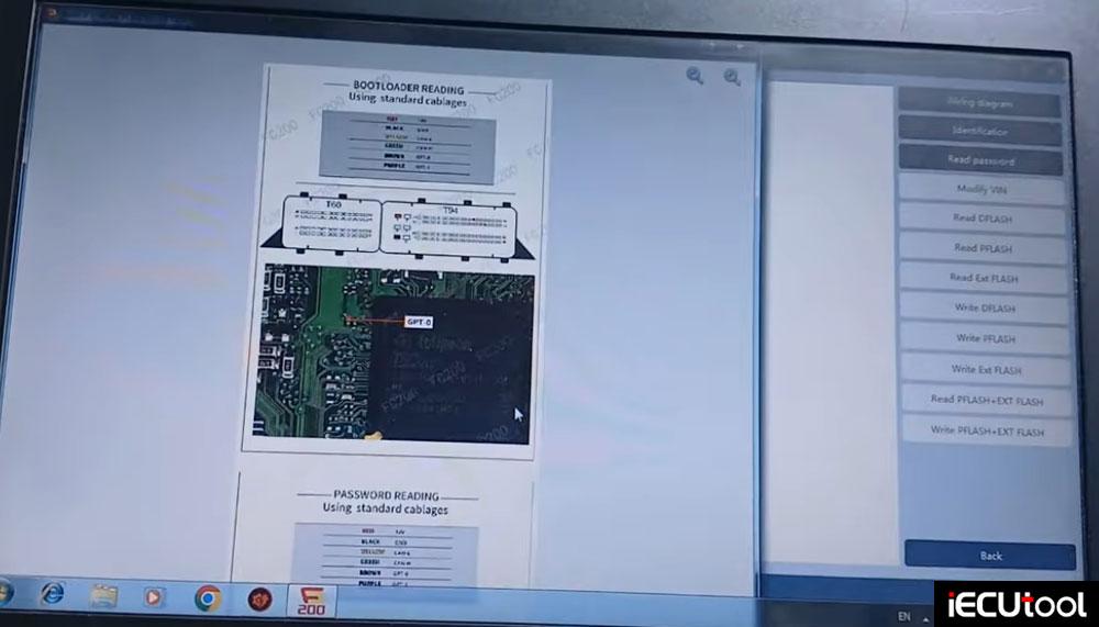
The solution was to use a “Version 2” connection diagram for boot mode, which requires a physical modification to the ECU’s circuit board.
Two resistors must be soldered onto a specific integrated circuit (IC) on the ECU board. The diagram called for two 470-ohm resistors.
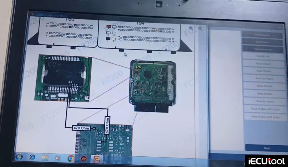
He has no two 470ohm resistors in hand. Then he used three 150-ohm resistors in series for each point, achieving a total resistance of approximately 450 ohms—close enough for a successful connection.
Using a BDM frame for stability, the resistors were carefully soldered onto the designated points on the IC.
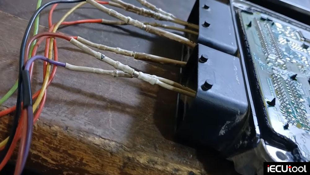
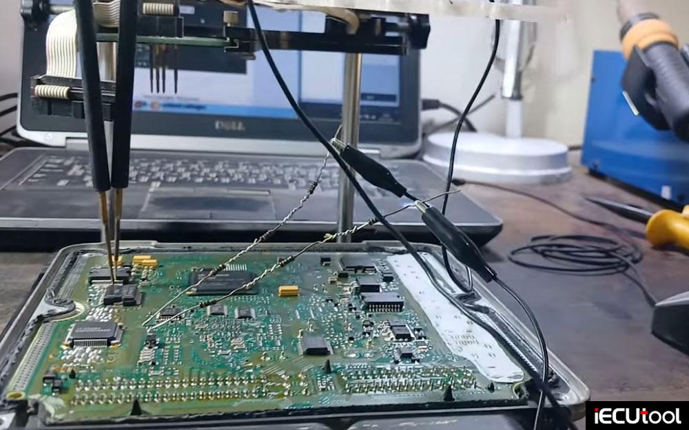
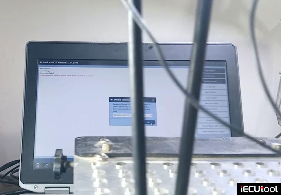
With this custom connection in place, the software was able to successfully read the password directly. The password file was saved to the desktop for the next step.
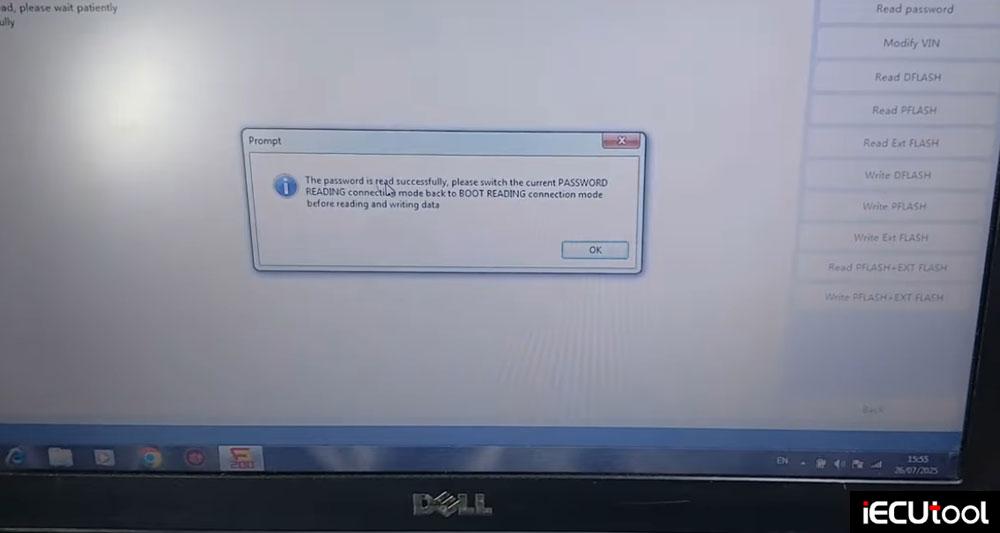
Load password file to read Dflash and Pflash data. Then save data.
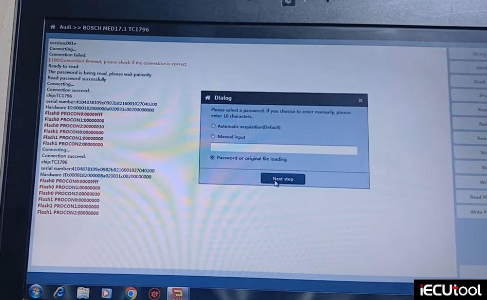


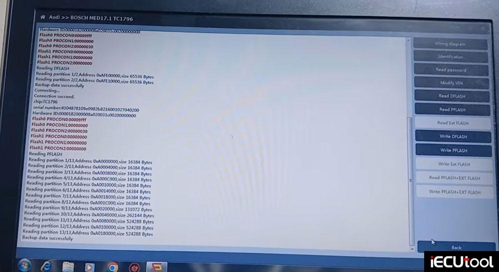
Reading the ECU Data
After successfully reading the password, the hardware setup needs to be reconfigured for data reading and writing.
1. Reconfiguring the Connection:
The temporary resistors were desoldered and removed.
Following the “boot reading connection mode” diagram, a wire (a brown one in this case) was soldered to a specific point on the board.
The standard connections—power, ground, and the two CAN wires—were established.
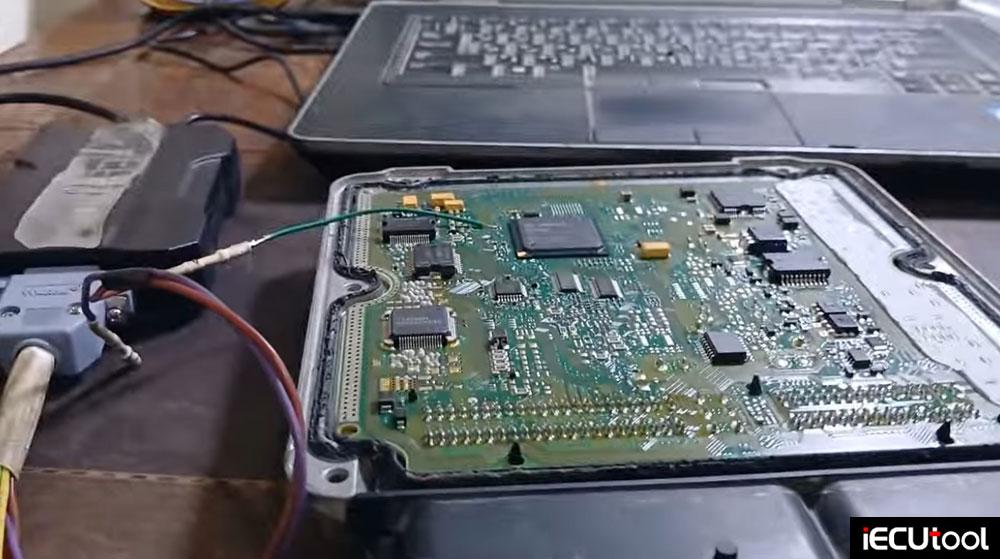
2. Reading the Flash Memory:
With the new connection, the “Identification” was successful.
The software then prompted for the password. The previously saved password file was loaded.
Read both the P-Flash and D-Flash data, saving these critical files to the desktop.
Writing the ECU data.
Modify the immo file.
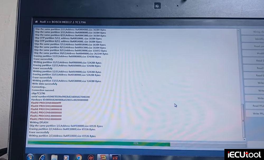
Write the modified D-flash and P-flash back to ECU with FC200 programmer.
After both files were written, the Immo Off procedure was complete.
Crucial Points to Remember:
Patience is Key: This is not a plug-and-play process. It requires careful soldering and multiple connection steps.
Hardware Modifications are Necessary: Be prepared to make physical changes to the ECU board, as boot mode often requires it.
Backup Everything: Always read and save the original flash files and the password before making any changes.
Stable Connection: A reliable connection to the ECU’s circuit board is paramount for successful communication throughout the process.

